
What Is a Flex Circuit PCB?
Flex Circuit PCB
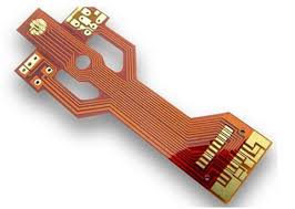
A flex circuit pcb is a flexible printed circuit board that can be used in a wide variety of applications. These include computer monitors, mobile phones, and tablet computers. Flex circuits offer a number of advantages over traditional rigid boards, including reduced weight and size. They are also more durable, allowing them to endure repeated bending and movement. They are also easier to mount than rigid boards.
A specialized manufacturing process allows flex circuits to be built quickly and efficiently. The fabrication method combines the layers of copper, adhesives, and laminate materials to create a finished product. The flex circuit pcb can then be cut to length and soldered together. After assembly, the flex circuit can be tested to ensure that it works properly.
There are many different types of flex circuits, each designed for a specific purpose. They can be single or double-sided, and can have different trace patterns on each side. They can also have different dielectric layers. Some flex circuits are insulated with different films, such as PI and PET, or a combination of glass fiber and epoxy. In some cases, the circuits are covered with solder mask ink.
What Is a Flex Circuit PCB?
The choice of material is crucial in designing a flex circuit. If the design is for a static application, then an electrodeposited (ED) copper is an ideal choice. However, if the flex circuit will be subjected to dynamic bending and movement, then a higher-grade rolled annealed copper is necessary. This type of copper is able to stretch further before fatigue cracking occurs and is springier in the z direction, which will improve the flex circuit’s ability to withstand dynamic bending.
Another key consideration in flex circuit design is the use of shielding to reduce electromagnetic interference (EMI). Shielding methods can include solid copper layers, silver inks, or specialized films. The shielding must also meet reference plane and EMI criteria, and it must be capable of supporting controlled impedance.
Other important considerations include the choice of trace width and spacing. Wider traces can lead to I-beaming, which causes stress points that can cause copper circuits to break. To avoid this, designers should stagger traces on both sides of the flex circuit and make sure they transition from wide to narrow traces gradually. They should also avoid discontinuities like vias, slits, cut-outs, and holes near the bend area.
Stiffeners are also used to increase a flex circuit’s durability. They can be placed on both the conductive and non-conductive sides of the substrate, and can vary in thickness. They can help to relieve strain, balance weight and heat dissipation, and reinforce solder joints.
Other important considerations are the choice of a fabricator and assembly process. A reputable PCB manufacturer can provide a turnkey solution that includes flex circuit assembly, fabrication, and testing. They will also have a strong track record of meeting customer requirements. The CM should also be able to provide real-time supply chain data and access millions of ready-to-use components.